Filter Housings

Filter Housings

Der Gebrauch von RO-Membranen ist seit Einführung im industriellen Maßstab, Mitte 1960, rasch angestiegen. Durch die Entwicklung und Markteinführung von Thin-Film-Composite im Jahre 1977 wurde die Umkehrosmose-Technologie zukunftsweisend weiterentwickelt. Heute wird eine Vielzahl von Thin-Film-Composite Membranen (Polyamid) vermarktet.
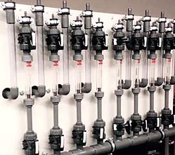
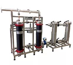
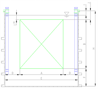
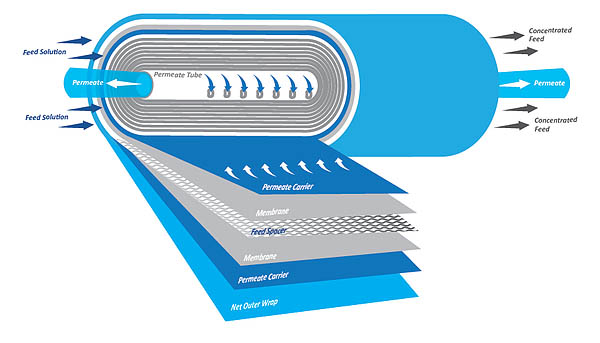
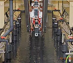
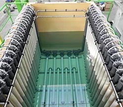
Dabei gibt es eine Reihe verschiedenster Konfigurationen; vom Platten-Rahmen-System über Rohr-Systeme bis hin zum gebräuchlichsten System, dem Wickelmodul, die auch anwendungsspezifische Bedeutung haben.

Eine Vielzahl von Anwendungen haben sich entwickelt und „traditionelle“ Verfahren abgelöst. Die weitaus häufigste Anwendung ist unter dem Oberbegriff Wasseraufbereitung zu finden. Dazu gehören Verfahren wie Enthärtung und Entsalzung von Grund-, Brunnen-, Oberflächen- und Kesselspeisewasser. Auch die Entfernung von TOC, Pestiziden, Herbiziden und anderen Umweltgiften aus Trinkwasser wird heute von RO-Membranen geleistet.

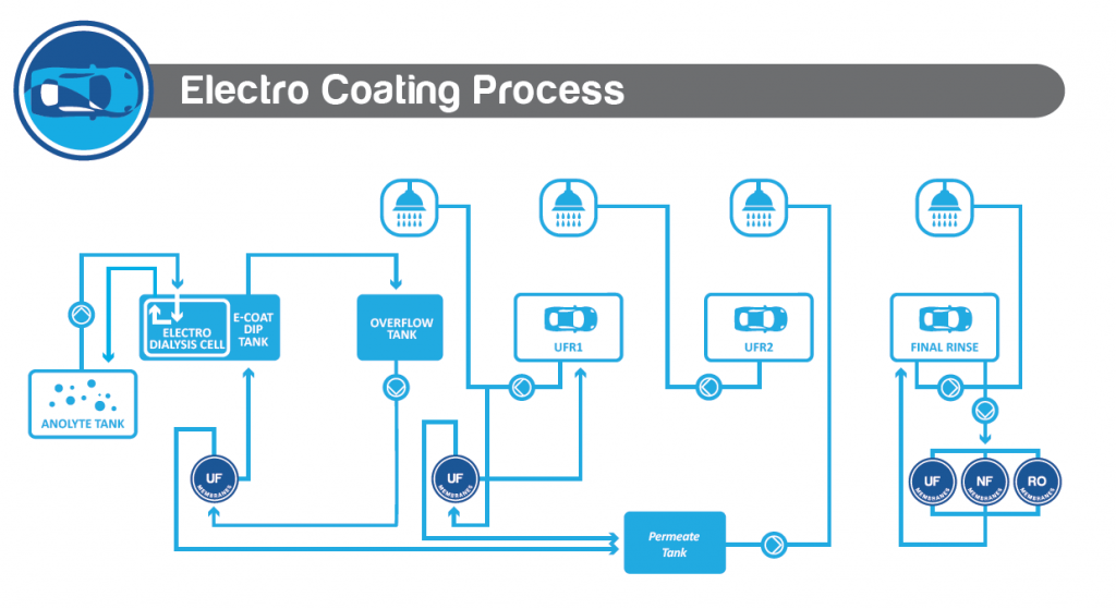
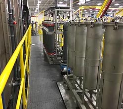
Daneben hat sich auch in anderen Industriebereichen die Umkehrosmose als eine Standardtechnologie etabliert. Bei der Prozeßstromkonzentierung in der Automobilindustrie oder in der Abwasseraufbereitung mit Kreislaufführung hat sich dieses Verfahren bereits bestens bewährt.

Durch eine veränderte Betrachtung dieser Technologie weg von der technischen Sicht “was ist möglich”, hin zu der kaufmännischen Sicht “was kostet sie”, sind neue Anforderungen an die Membranentwicklung entstanden.

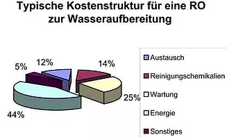
Die Wirtschaftlichkeit einer LG Chem Membrane (und damit häufig auch einer neuen Anwendung ) orientiert sich an folgenden Kriterien: 

  • Energieaufwand
  • Arbeits- / Wartungs- / Betreuungsaufwand
  • Austauschkosten der Membran
  • Chemikalienaufwand bei Reinigung und Produktion
  • Investitionskosten

Fouling / Scaling („Low-Fouling“-Membran”)

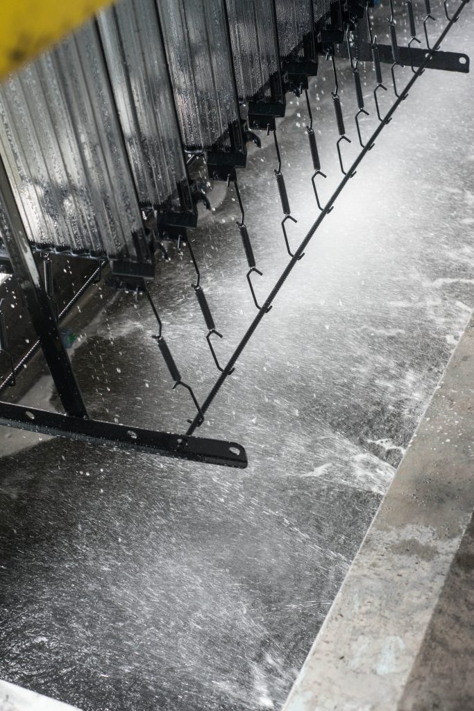
Durch die Auswahl von Membranmaterialien und durch entsprechende Fertigungsschritte bei der Membranherstellung ist es möglich, optimierte Membranen für verschiedenste Prozesse bereitzustellen, um prozessbedingtes Fouling gering zu halten. Unterstützt wird dies auch durch die Verfahrenstechnik wie z.B. ein höherer Cross Flow. Durch den gezielten Einsatz von Antiscaling-Mitteln in den Zulauf einer RO-Anlage oder in Kombination mit Enthärtungsverfahren, kann ein Scaling kontrolliert werden.

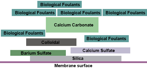
Weitere Punkte sind die Lebens- / Standzeitverbesserung und der damit in Zusammenhang stehende benötigte Chemikalieneinsatz bei der Reinigung von Membranen. Hier hat die chemische Industrie entsprechende Chemikalien entwickelt, die die Membran weniger chemisch angreifen, aber erheblich besser reinigen. Durch den Einsatz dieser Stoffe werden auch die Arbeits- und Wartungskosten des Bedienungspersonals erheblich gesenkt. Durch chemische Modifikation werden ausgesprochene „Anti-Fouling“- Membranen vom Typ AFR produziert. Einige Hersteller weisen dieses Verhalten marketingträchtig als besondere Eigenschaft aus. LG AFR-Elemente weisen diese günstige Produkteigenschaft bereits seit ihrer Markteinführung auf und stehen als HR.

Anolyte Systems

Anolyte Systems

The method of electrophoretic painting is one of the most progressive technologies of surface finishing of metal products. The development of the cataphoretic technology is led by the automotive industry since all car producers have focused on corrosion resistance of bodies and other components. High quality of surface finishing, together with favourable economic and ecological conditions, predetermined this technology for use also in other branches of mechanical engineering and consumer Industry.

Cataphoresis is a method of paint application in an electrochemical way. The painted object is connected as a cathode in a direct current field of the electrolyte (water solution of paint) and cations of paint are deposited on it. Electrophoretic cell with the ion-exchange membrane (desk or tubular) is connected as an anode and serves both as a counter-electrode and for maintaining a concentration balance in the paint bath.

In electro-dialysis, the presence of Cl and O2 ions can produce an extremely rapid intragranular corrosion of the steel electrode.Therefor it is nessesery the flush the Electrode continuously with Anolyte. Another point is the cooling of the electrode.Conductivity measurement instruments make it possible to check on the level of acidic ions produced by the electro-dialysis process.Flow meters are needed for each individual ED Cell to make sure that the flow is adjusted acording to Ampere density.A conductivity meter placed in the anolyte circuit does maintaining the conductivity setpoint values ​​specified by the paint manufacturer. This controls an electric valve adding demineralized water (DI) and regulates the acid concentration at the setpoint values. The recommended conductivity varies according to the types of paint and the manufacturers between 600 and 6000 µS / cm. During the process, negatively charged acidic anions are formed and migrate from the cathode to the anode. These molecules pass through the membrane toward the electrode and are trapped in the ED Cell (membrane / electrode interface) where they form an acid molecule with H + according to the dissociation reaction of the paint.
Heydkamp Membrane Technology can provide the complete equipment to make sure that your process is save and effective.


Complete UF/NF Systems

Complete UF/NF Systems

Ultrafiltration is a pressure-driven membrane process capable of separating soluble components on the basis of molecular size and shape. Under an applied pressure difference across an ultrafiltration membrane, solvent and small solute species pass through the membrane and are collected (permeate) while larger solute species are retained by the membrane and recovered as a concentrated Retentate. In Electrocoat paint systems, the ultrafiltration permeate contains water and paint solubilizers. The Permeate is used in the paint line rinse section. This recycling method provides a closed loop rinse system for recovering paint solids (drag-out). The Permeate can also be diverted to drain to reduce conductivity of the paint. The filtrate capacity refers to the membrane cartridge surface area at a certain paint recirculation capacity and is known as the “specific filtrate capacity”. It depends on the type of paint used and must be determined from case to case by way of measurement.

Nanofiltration — Final Rinse (FR)

  • Reduce cost of fresh DI water, spent water treatment and discharge
  • Reduce energy usage
  • Reduce total cost of operation (TCO)
  • better Quality due to less ressin in the permeate

The benefits of Solecta’s FR technology were evidenced by the results of a recently-completed project for a large automotive client. The client challenged Solecta to find a way to reduce the consumption of fresh water in the final rinse stage of the e-coating process; reduce wastewater treatment costs without jeopardizing final finish quality; and reduce paint costs by maximizing recovery
of valuable paint solids. Understanding the complex interconnections and variations in chemical compositions among the anolyte, the rinse and the final rinse baths, coupled with a detailed audit of the system, enabled Solecta to recommend that its client incorporate its FR
technology in the e-coat process. This would address the client’s three challenges. First, it would allow water from the closed-loop rinse system to be used in the final rinse step, eliminating the need for fresh water. Second, the Solecta technology would enable the final rinse water to be reused in the previous rinse step, extending the closed-loop water system. Third, the client would be able to recover the valuable paint particles from the final rinse. Detailed analysis ensured that there would be no detrimental impact on the composition of the anolyte bath or its stability and no negative impact on the final e-coat product quality.

Process description

Prefilter Systems

Prefilter Systems

New Pre filter system shiped:

Shortly before shipping you can see one of our new projects here. Pre-filter systems for degreasing baths, sinks and electrodeposition paint. All filters in “Fast-Open” design, material: 304 and 316L.

in the shipment:

  • 120 pieces of electro dialysis cells, 4,200mm long
  • Anolyte distribution System
  • Permeate / sealing water tank combination
  • UF system for 6 Unidesign compact modules including individual flushing device
  • CIP Tank
  • Anolyte Unit
  • Rectifier Thyristor Technology 5000A (Wächter, Remscheid)
    automatic Paint dosing system LNK incl. Touch panel

Electro dialysis Cell

Electro dialysis Cell

Elektrophoreseprinzip

The method of electrophoretic painting is one of the most modern technologies for the surface treatment of metal objects. The automotive industry has the largest share in the development of cataphoretic technology, where the anti-corrosion resistance of car bodies and other components is the focus of interest of all producers. The high quality of the surface treatment, together with the advantageous economic and ecological conditions, has predetermined this technology for use in other mechanical engineering and consumer industries.

Cataphorese

Cataphoresis is a method for electrochemical paint application, in which the object to be painted is connected cathodically to direct current in the electrolyte (aqueous paint bath) and then color cations are deposited on the article. The electrophoretic box with an ion exchange membrane (plate or tubular) is connected as an anode and serves firstly as a counter electrode and secondly to maintain the concentration balance in the paint bath.

Electrode (Anode)

The round cell EFC-Anodex is a cylindrical system, which on the one hand ensures the function of the counter electrode to the cathode and on the other hand enables the excess anions to be continuously separated from the cataphoresis bath thanks to the anex membrane.The cylindrical anode is located in the middle of the EFC cell so that the construction of the lower lid and upper head ensures their desired centering. This construction also allows the anode to rotate freely when the top head screw is loosened, which ensures more uniform wear of the anode material due to the electrochemical solution during the cataphoresis process.

Ion-Exchange Membrane RALEX MEMRANE® Type AMH-HD

The anex membrane is installed in such a way that it is potted in the lower lid and upper head and is reinforced with a perforated PP tube. The perforated tube delimits the space between the membrane and electrode for effective anolyte flow, and its structure enables the required passage of electrical current.There is no expansion of the membrane with loss of free electrode area! In contrast to an extruded membrane, the expansion of which can be up to 15% depending on the bath parameters, the space in the lower pool area is fully utilized. This allows more space to be installed per cell. This is particularly useful in the floor area.

Kopf der Elektrodialyse Zelle

The head construction ensures the required tightness of the entire system and is used for attachment to the pool edge. A hose nipple in the middle of the anode serves as the inflow of the anolyte. The recycling of the anolyte ensures a sufficient and even anolyte circulation and an effective discharge of the acid substance (O2) generated on the anode surface during the electrochemical process.The electrical connection to a direct current source is also part of the design.

Auslegung / Angebot

Um Ihnen ein Angebot über Elertrodialyse Zellen / Membranen zu erstellen benötigen wir nur wenige Angaben wie Kopflänge der Zelle sowie die aktive  Membranelänge. Alternativ können wir mittels unserer Auslegungssoftware ihre bestehende Konfiguration überprüfen bzw, optimieren.

Hierzu benötigen wir folgende Angaben

  • Bauteilhöhe [B]
  • Oberfläche pro Warenträger getaucht
  • Beckenhöhe [H]
  • Höhe zwischen oberer Beckenrand und Lackniveau
  • Lackniveau und Bauteil [I]

Gerne stehen wir Ihnen auch persönlich bei Fragen zur Qualitätsoptimierung, Produktionserweiterung und Problemlösung zur Verfügung.

Design data

Please download the PDF document and fill out the form fields. We will find the best solution for your process according to your specifications.

Spiral Elements

Spiral Elements

A spiral wrap element consists of several layers of flat membranes, spacers and drainage fleeces (permeate carriers), which are rolled up in a spiral to form a wrap (Fig. 1). In the center of the element is the permeate collecting tube, which leads the permeate taken out through the front of the module housing. The sealing is done by an adapter which is equipped with O-rings.

The active separating layer of the asymmetrical semipermeable membrane is located on both sides of the spacer (also called spacer) and is characterized by high mechanical strength and robustness.

The spiral winding element essentially consists of the membrane module, which is inserted in a housing. This can be PVC or Stainless steel.

In order to prevent individual layers of the membrane or spacer from telescoping due to the constant overflow of the module, so-called ATD’s (Anti Telescope Devices) are also inserted into the housing.